Genie GTH-5519 Service Manual: A Comprehensive Overview (04/14/2026)
Today‚ April 14th‚ 2026‚ this manual provides essential guidance for the Genie GTH-5519‚ acting as a crucial roadmap for operation and upkeep․
Reviewing the Genie GTH-5519 Fuse Box Diagram within the package is paramount‚ alongside accessing the detailed spec sheet and lift charts for optimal performance․
The Genie GTH-5519 is a versatile and compact telescopic handler designed for a wide range of material handling applications․ This service manual is specifically created to assist technicians and operators in the safe and efficient maintenance‚ repair‚ and operation of this machine․ Understanding the intricacies of the GTH-5519 is crucial for maximizing its performance and longevity․
This manual details everything from routine inspections to complex repairs‚ ensuring that all work is carried out to the highest standards․ It’s vital to thoroughly review this document before undertaking any service or maintenance procedures․ The GTH-5519 boasts a 19-foot lift height and a 5‚500 lb capacity‚ making it ideal for construction‚ agriculture‚ and industrial settings․
Proper utilization of the Genie GTH-5519 Fuse Box Diagram and accompanying lift charts‚ as referenced in initial documentation‚ is essential for safe operation․ This manual serves as a comprehensive resource‚ empowering users to maintain peak operational efficiency and address potential issues proactively․
Safety Precautions & General Information
Prior to any operation or maintenance on the Genie GTH-5519‚ a complete understanding of these safety precautions is paramount․ Always disconnect the battery before performing any electrical work‚ and ensure the machine is parked on a level surface with the parking brake engaged․ Wear appropriate personal protective equipment (PPE)‚ including safety glasses‚ gloves‚ and steel-toe boots․
Never exceed the machine’s rated capacity‚ and always consult the Genie GTH-5519 Lift Charts for load limits at various heights and reaches․ Be aware of overhead obstructions and surrounding personnel․ Thoroughly inspect the machine before each use‚ paying close attention to hydraulic hoses‚ cylinders‚ and structural components․
This manual assumes a basic level of mechanical knowledge․ If you are not comfortable performing a specific task‚ consult a qualified technician․ Familiarize yourself with the location of emergency shut-off switches and fire extinguishers․ Adherence to these guidelines will significantly reduce the risk of accidents and ensure safe operation․

Technical Specifications
This section details the Genie GTH-5519’s core technical data‚ encompassing engine performance‚ hydraulic system parameters‚ and a comprehensive overview of electrical components․
Engine Details (Model & Performance)
The Genie GTH-5519 is typically equipped with a reliable and robust engine‚ designed for demanding telescopic handler applications․ While specific engine models may vary based on manufacturing date and regional specifications‚ it commonly features a Tier 4 Final compliant diesel engine․
Key engine specifications generally include a displacement around 4․5 liters‚ delivering a horsepower rating of approximately 74 hp (55 kW)․ This power output provides sufficient capacity for lifting operations and maneuvering on diverse terrains․ The engine is engineered for optimal fuel efficiency and reduced emissions‚ adhering to stringent environmental standards․
Performance characteristics encompass a maximum torque output of around 220 lb-ft‚ enabling strong pulling force and responsive operation․ The engine’s cooling system is designed to maintain optimal operating temperatures even under heavy loads and in hot ambient conditions․ Regular maintenance‚ as outlined in this manual‚ is crucial for preserving engine performance and longevity․
Hydraulic System Overview
The Genie GTH-5519’s hydraulic system is the core of its lifting and maneuvering capabilities․ It’s a closed-center‚ load-sensing system‚ designed for smooth‚ precise control and efficient power delivery․ This system utilizes a high-pressure hydraulic pump‚ typically delivering around 3‚000 psi‚ to power the boom lift‚ tilt‚ and steering functions․

Key components include the hydraulic reservoir‚ filters‚ pump‚ control valves‚ and cylinders․ The system employs robust hydraulic hoses and fittings to ensure reliable fluid transfer․ Load-sensing technology adjusts pump output based on demand‚ minimizing energy consumption and heat generation․
Regular maintenance of the hydraulic system is vital․ This includes checking fluid levels‚ inspecting hoses for leaks or damage‚ and replacing filters according to the schedule outlined in this manual․ Proper hydraulic fluid selection is also critical for optimal performance and component protection․
Electrical System Components
The Genie GTH-5519 relies on a 12-volt electrical system to power various functions‚ including starting‚ lighting‚ instrumentation‚ and control circuits․ Key components include the battery‚ alternator‚ starter motor‚ and a comprehensive network of wiring harnesses․
A crucial element is the fuse box‚ protecting circuits from overloads․ (Refer to the Fuse Box Diagram in the Component Breakdown section for detailed layout and fuse ratings)․ The system also incorporates safety switches‚ such as emergency stop buttons and tilt sensors‚ to prevent unintended operation․
Diagnostic capabilities are enhanced through onboard controllers and potentially‚ diagnostic ports for troubleshooting․ Regular inspection of wiring for damage‚ corrosion‚ and secure connections is essential․ Maintaining proper battery charge and alternator function ensures reliable system operation․ Always disconnect the battery before performing any electrical repairs․

Maintenance Procedures
Consistent upkeep is vital for the GTH-5519’s longevity․ This section details routine inspections‚ fluid checks‚ and filter replacements‚ ensuring peak performance and safety․
Routine Inspection Checklist

Prior to each operation‚ a thorough inspection is crucial for safe and efficient GTH-5519 performance․ Begin with a visual check of the tires‚ noting any damage or uneven wear․ Inspect all hydraulic hoses and fittings for leaks or cracks‚ paying close attention to cylinder rods․
Next‚ examine the boom and carriage for structural integrity‚ verifying proper pin lubrication․ Check the functionality of all safety devices‚ including the emergency stop switch and the load sensing system․ Confirm the operator’s seatbelt is in good working order․
Furthermore‚ inspect the fuel level‚ engine oil‚ hydraulic fluid‚ and coolant levels‚ topping off as needed; Verify the proper operation of lights‚ signals‚ and the horn․ Finally‚ review the fuse box diagram to ensure all fuses are intact․ Document all findings and address any issues before operating the machine․
Fluid Level Checks & Replacements
Maintaining correct fluid levels is vital for the GTH-5519’s longevity․ Regularly check the engine oil using the dipstick‚ adding SAE 10W-30 as needed․ Inspect the coolant level in the radiator‚ ensuring it’s filled with a 50/50 mix of antifreeze and water․
Hydraulic fluid levels should be checked with the boom lowered․ Use the specified hydraulic oil type‚ referencing the technical specifications․ Monitor the fuel gauge and replenish with diesel fuel as required‚ filtering during the process․

For replacements‚ follow these guidelines: engine oil every 250 hours‚ coolant every 1000 hours‚ and hydraulic fluid every 500 hours․ Always dispose of used fluids responsibly‚ adhering to local regulations․ Refer to the fuse box diagram for electrical component fluid considerations․ Proper fluid maintenance prevents costly repairs and ensures optimal performance․
Filter Replacement Schedule

Consistent filter replacements are crucial for maintaining the GTH-5519’s performance and preventing component damage․ The air filter should be inspected every 250 hours and replaced every 500 hours‚ or sooner in dusty conditions․
Fuel filters require attention every 500 hours‚ safeguarding the engine from contaminants․ Hydraulic filters‚ vital for system efficiency‚ should be replaced every 1000 hours․ Cabin air filters‚ if equipped‚ benefit from annual replacement for optimal air quality․

Regularly check the condition of all filters during routine inspections․ Referencing the Genie GTH-5519 Fuse Box Diagram can help locate filter access points․ Proper filter maintenance extends component life and ensures reliable operation․ Always use manufacturer-approved filters for best results and avoid compromising system integrity․
Troubleshooting Common Issues
Addressing operational challenges swiftly is key․ This section details solutions for starting problems‚ hydraulic malfunctions‚ and electrical faults within the GTH-5519․
Starting Problems & Solutions
Diagnosing starting issues on the Genie GTH-5519 requires a systematic approach․ First‚ verify the battery charge and connections‚ ensuring they are clean and secure․ A low battery is a frequent culprit․
Next‚ inspect the starter solenoid and starter motor itself for proper function; listen for a clicking sound when attempting to start‚ which could indicate a solenoid issue․ Check the fuel supply – a clogged fuel filter or empty tank will obviously prevent starting․
Furthermore‚ examine the ignition switch and safety interlocks․ The GTH-5519 incorporates multiple safety features that can inhibit starting if not properly engaged․ Refer to the fuse box diagram to check for blown fuses related to the starting circuit․ Finally‚ if the engine cranks but doesn’t fire‚ investigate potential issues with the fuel injection system or spark plugs (if applicable)․
Hydraulic System Malfunctions
Addressing hydraulic issues on the Genie GTH-5519 begins with checking fluid levels․ Low fluid is a common cause of performance problems․ Inspect hoses and fittings for leaks‚ paying close attention to cylinder connections and the pump․
Slow or erratic movements often indicate a failing hydraulic pump or a clogged filter․ Regular filter replacement is crucial for maintaining system health․ If the boom drifts or fails to hold position‚ suspect internal leakage within the lift cylinders․
Furthermore‚ examine the hydraulic oil for contamination; dirty oil can damage components․ Check the operation of the control valves to ensure they are functioning correctly․ Consult the electrical schematics for any related electrical faults affecting the hydraulic system․ Proper diagnosis requires a thorough understanding of the system’s components and their interactions․
Electrical System Faults

Diagnosing electrical problems on the Genie GTH-5519 starts with a visual inspection of the fuse box diagram․ Blown fuses are often the first sign of an electrical issue․ Check for loose connections‚ corroded terminals‚ and damaged wiring harnesses․
If the machine fails to start‚ verify the battery voltage and the functionality of the starter solenoid․ Electrical schematics are essential for tracing circuits and identifying faulty components․ Intermittent operation can indicate a failing sensor or a loose connection;
Pay close attention to the control panel and its associated wiring․ Ensure all switches and indicators are functioning correctly․ Refer to the service manual for specific troubleshooting procedures related to each electrical component․ Remember to disconnect the battery before performing any electrical repairs to prevent accidental shorts․
Component Breakdown & Repair
Detailed diagrams and schematics facilitate disassembly and repair of the GTH-5519․ Accessing the fuse box diagram and understanding electrical layouts are crucial for effective maintenance․
Fuse Box Diagram & Electrical Schematics
Understanding the electrical system is paramount for diagnosing and resolving issues within the Genie GTH-5519․ This section provides a comprehensive fuse box diagram‚ clearly labeling each fuse and its corresponding circuit․ Refer to this diagram before attempting any electrical repairs to prevent further damage or safety hazards․
Alongside the fuse box layout‚ detailed electrical schematics are included‚ illustrating the wiring pathways and component connections throughout the machine․ These schematics are essential for tracing circuits‚ identifying short circuits‚ and performing accurate repairs․ Carefully study these diagrams in conjunction with the fuse box information to gain a thorough understanding of the electrical system․
Always disconnect the battery before working on any electrical components․ Use a multimeter to verify the absence of voltage before proceeding․ Incorrectly performed electrical repairs can lead to serious injury or machine malfunction․ Prioritize safety and consult a qualified technician if you are unsure about any aspect of the electrical system․
Lift Cylinder Repair & Maintenance
Maintaining the lift cylinders is crucial for the safe and efficient operation of the Genie GTH-5519․ This section details procedures for inspecting‚ repairing‚ and maintaining these vital components․ Regular inspection should include checking for leaks‚ damage to the cylinder walls‚ and proper operation of the seals․
Repair procedures cover common issues such as seal replacement and cylinder re-boring․ Always use genuine Genie replacement parts to ensure compatibility and performance․ Before disassembly‚ relieve all hydraulic pressure․ Exercise extreme caution when working with pressurized hydraulic systems․
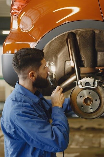
Preventative maintenance includes lubricating the cylinder rods and pivot points․ Keep the rods clean and free from debris to prevent seal damage․ Regularly inspect the hydraulic hoses connected to the cylinders for wear and tear․ Promptly replace any damaged hoses to avoid hydraulic fluid leaks and potential safety hazards․
Appendices
Included are vital Genie GTH-5519 lift charts‚ providing critical load capacity information for safe operation․ These charts are essential for all operators and personnel․
Genie GTH-5519 Lift Charts
Genie GTH-5519 lift charts are indispensable tools for ensuring safe and efficient operation of the telehandler․ These charts detail the machine’s lifting capacity at various boom lengths and angles‚ crucial for preventing overloads and potential accidents․ Always consult the appropriate lift chart before any lifting operation‚ considering the load weight‚ lift height‚ and boom configuration․
The charts provide maximum load capacities for both forward reach and upward lift‚ clearly indicating limitations based on stability․ Understanding these limitations is paramount for responsible operation․ Factors like tire condition‚ ground slope‚ and outrigger placement (if applicable) can also affect lifting capacity and should be considered alongside the chart data․
Terex AWP’s two-page spec sheet includes these vital lift charts‚ offering a quick reference guide for operators․ Regularly review and familiarize yourself with the charts to maintain a safe working environment․ Proper utilization of these charts is not just a best practice‚ but a critical safety requirement․